06. Simple Control Diagrams
C3 L2 L4 Control Diagrams V1

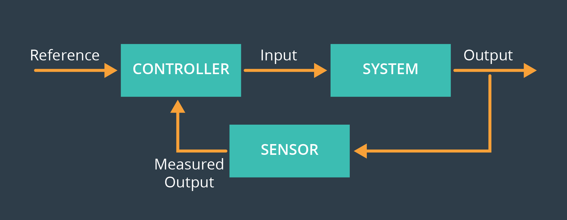
The control diagram is pretty general. The table below should help you understand what it means in the context of a 1D drone. Note that in this lesson we are assuming we have perfect sensors, so the measured output is the same as the true output.
| Control Diagram | Monorotor |
|---|---|
| Reference | z_{\text{target}} (target position) |
| Output | z (true position) |
| Input | u_1 (commanded thrust) |